The heart of using Time Shaper successfully is the selection of the "synthetic shutter" to render the motion look best suited to your scene. This can be a bit daunting, as Time Shaper offers a wide variety of shutters to tailor the look of motion. Here's an introduction to these options and their trade-offs.
What is a "Synthetic Shutter"?

A shutter waveform shown in Time Shaper. Each blue bar represents an incoming frame, and the height of the bar indicates how much weighting it will get in the output frame. The yellow lines show the length of an output frame.
Time Shaper uses the high-frame-rate footage to synthesize new shutters for normal-frame-rate output. For instance, if incoming footage were shot at 120 fps and the output footage will be at 24 fps, there is one output frame produced for every five input frames. If we were to just average together every five input frames, treating every frame equally, we would produce output frames that had imagery evenly exposed for a full 1/24th of a second, which would be a 360º square wave shutter. Time Shaper extends this idea by doing a weighted average of the incoming frames, so not every input frame is treated equally in the output frames. Also, Time Shaper can use more than five frames to create the output frame, meaning input frames are re-used, or overlapped, between output frames. Further, Time Shaper can even subtract some input frames, rather than adding them in. This allows Time Shaper to synthesize shutters that would not be realizable in a physical camera, but which have motion and mathematical properties that are highly desirable.
The shutter waveform can be seen in the Time Shaper interface, and you can tell several things about the shutter from the waveform. First, you can see if it has any negative values, which mean that some input frames will be subtracted in the final output.
Subtracting some frames can yield a sharper frequency response falloff, which is desirable, but sometimes this can cause undesirable artifacts in the motion. A bright object moving across the screen will have leading and trailing dark bands from these subtracted elements. In playback, these dark bands are usually not directly perceptible by the viewer, and they usually are perceived as added image sharpness. However, in extreme cases these will become distracting.
Another thing to note is that a shutter waveform is not limited to just the five frames per output frame (in this example). In the figure, you can see that a "Normal" response shutter actually uses 19 incoming frames to form each output frame.
Because the shutters are synthesized from a higher frame-rate set of square-wave 360º shutters, the resulting waveform is not smooth, but is "stair-stepped". Shooting the input footage at even higher frame rates will increase the resolution of this synthetic shutter, and will result in even smoother and more accurate output.
The Modulation Transfer Function

A MTF graph from Time Shaper for the Tessive Magnesium shutter. Contrast is the Y axis, and frequency (related to speed of motion) is the X axis. As objects in the image move faster, their contrast reduces.
In order to understand the effect of any particular shutter on the rendering of motion, another graph can be very helpful. Time Shaper provides a graph called the "MTF", which stands for "Modulation Transfer Function".
Imagine a camera doing a simple pan of a scene. If the camera is panning very slowly, the background will have good contrast; it won't be very blurry at all. As the camera pans faster, we'd expect the background to become softer in each frame. It should lose contrast as the pan rate increases. Eventually, if we did a whip-pan, we wouldn't expect very much contrast at all in each frame. We would instead expect a very uniformly blurred image with low contrast.
The Modulation Transfer Function helps describe this situation as a single graph. To define some terms, "Modulation" means "contrast". "Transfer Function" means how the system (the camera) records or "transfers" this signal. So the graph really tells us how contrast changes when things move faster and faster in the scene. Contrast is the Y axis, and speed of movement (called frequency here) is on the X axis. The graph will show how the contrast of the image reduces as things move faster.
There are some special points of interest on the MTF curves. At 0 Hz (stationary), we expect full contrast, and this is defined as 100% contrast. Another point of interest is something called the Nyquist frequency, which is half the frame rate frequency. In our 24 fps output, this would be 12 Hz. This frequency is special, because it is the maximum real-world frequency that can be correctly recorded in the output footage. Any frequency above this will be "aliased", or distorted into some other signal between 0 Hz and the Nyquist frequency even though it was really a higher frequency signal. Time Shaper shows the area under the MTF curve that is above the Nyquist frequency in red to indicate that this region is adding noise to the output footage.
“The ultimate test is: does it look good?”
The green area in the Time Shaper MTF plot shows the signal that is recorded correctly under the Nyquist frequency. It is usually desirable that the green area be as large as possible while the red area be made as small as possible. An ideal shutter waveform would form a square response, filling the entire area under Nyquist with 100% contrast, while having 0% contrast above the Nyquist frequency. In practice, this kind of waveform would not look good at all.
Which brings us to the most important point: these graphs are here to aid you, but don't tell the whole story. The ultimate test is: does it look good? As you work with these options, the graphs help you identify what frequencies map to specific visual artifacts you are seeing, and help you accentuate them or reduce them as desired. They're just tools to help with that. Use them if you find them useful.
24 fps Shaped-Shutter Options

The Modulation Transfer Functions of Tessive Elemental shutters compared with a traditional 180º square-wave shutter.
Time Shaper offers five Elemental Shutters, Tessive Gallium, Tessive Magnesium, Tessive Silver, Tessive Beryllium, and Tessive Osmium. Each shutter has its own characteristics and trade-offs. See our page on Elemental Shutters for more detailed comparisons.
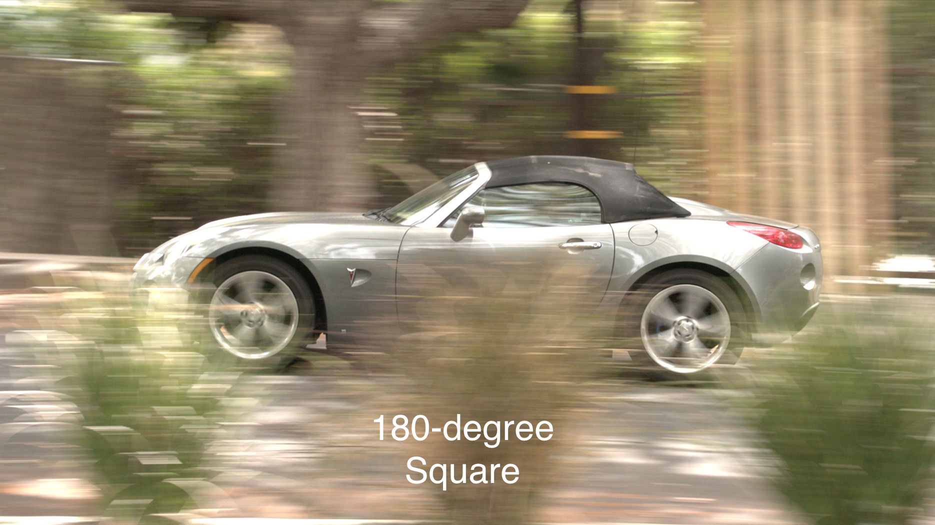
In the MTF graph shown, the four shaped shutters are compared with a traditional 180º square-wave shutter at 24 fps. Also, the Nyquist frequency (12 Hz) is indicated, as well as the frame rate (24 Hz). The traditional square-wave shutter has good contrast response below the Nyquist frequency, which is desirable, but it has an enormous amount of aliasing, which is the source of judder. The goal of Time Shaper is to preserve the detail we want but reduce or eliminate judder to the degree we can.
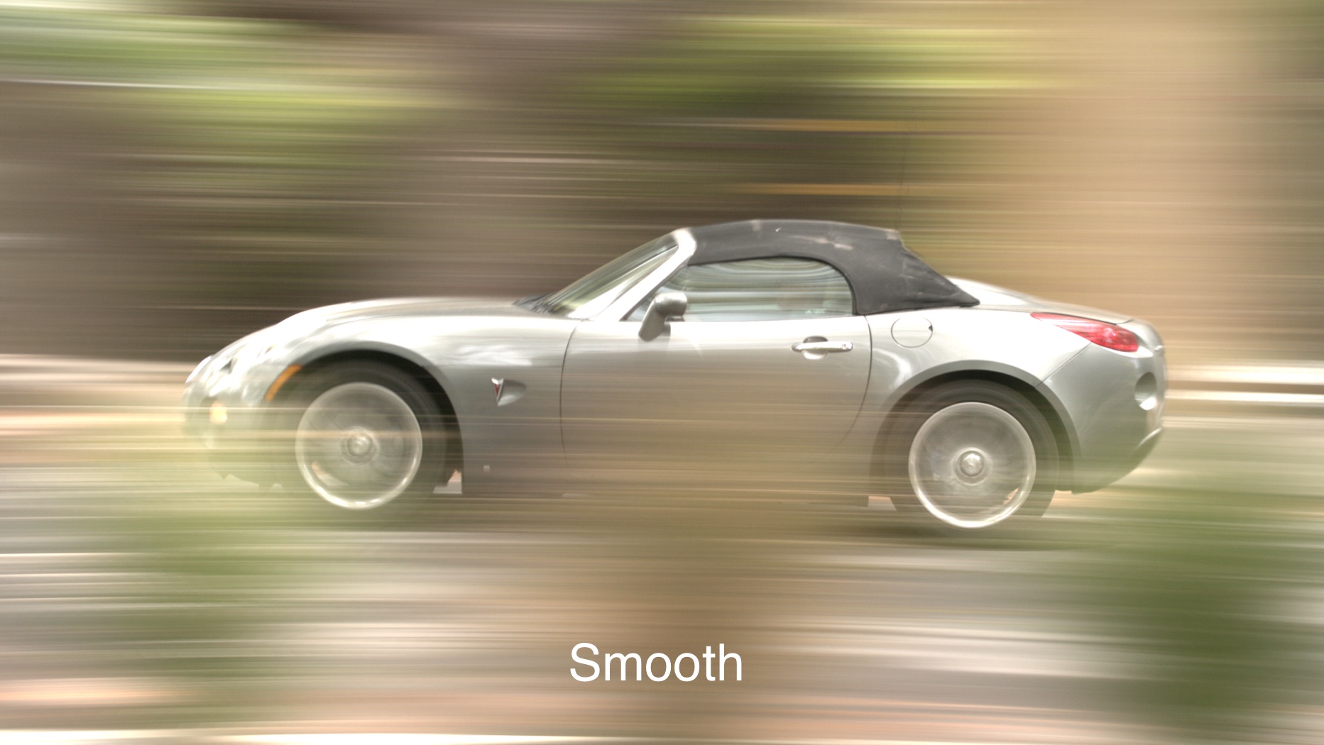
The Gallium shutter (green) virtually eliminates all judder. It has very little response above the Nyquist frequency. But neither does it have very good response below Nyquist. Notice that it has about half the signal below the Nyquist rate compared with the 180º square shutter. The Gallium shutter does indeed render motion very smoothly, but it is nearly judder free.
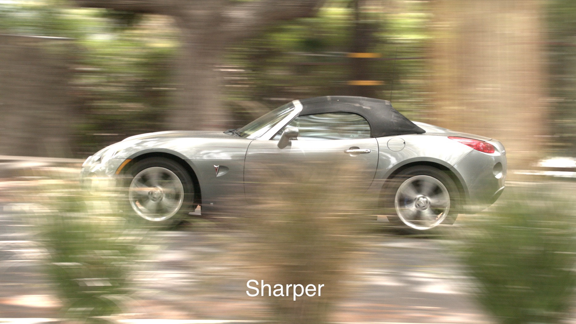
The Magnesium shutter (red) is designed to have reasonable frequency response below the Nyquist frequency, but be nearly 0 by the frame rate (24 Hz). Having little response at the frame rate frequency results in a nearly solid "persistence of vision" image. This means that a bright object moving across a dark background will leave a solid, unbroken line in the viewer's eye.
The Beryllium shutter (blue) more nearly matches the 180º square-wave shutter in the region below the Nyquist frequency, but again has almost no contrast at the frame rate frequency, yielding a solid "persistence of vision" image. The Beryllium shutter has more intense negative segments in the shutter waveform, followed by some outriding positive sections. This can result in "ringing" in the image, or very perceptible bands leading and trailing objects moving quickly in the scene. This may make it undesirable for certain action.
The Osmium shutter has a longer frequency rolloff, and suffers from less ringing than the Beryllium shutter, but does not reach low contrast values until well past twice the frame rate frequency. It closely matches the 180º shutter response, however, and does reduce judder. In many cases, it is a good substitute for a 180º shutter.